BRAM-COR VAPOR COMPRESSION DISTILLATION PROCESS
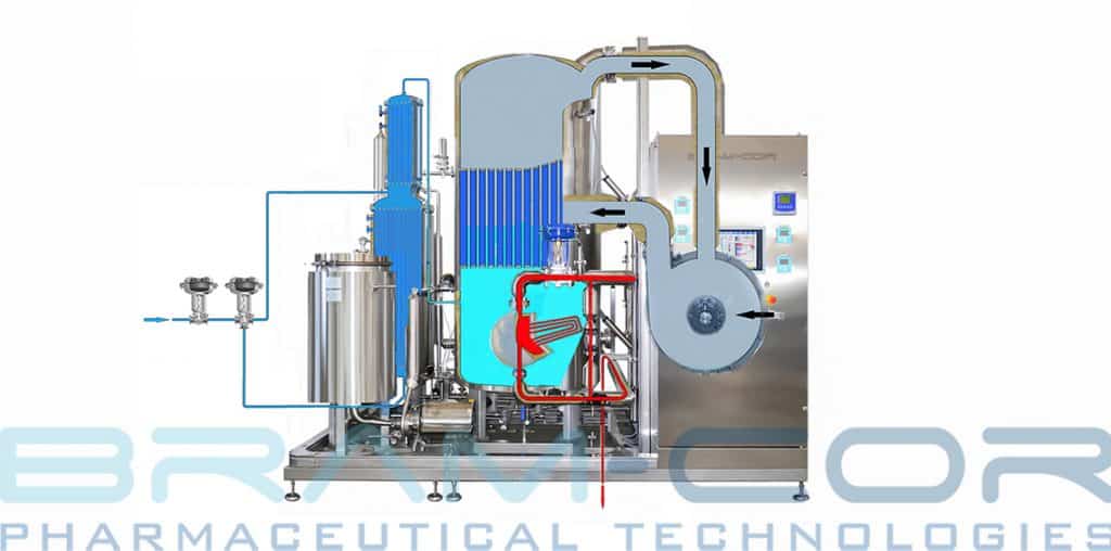
To understand how Vapor Compression Distiller works it is useful to discover the essential parts of the machine. In this diagram you can see a still with steam heating.
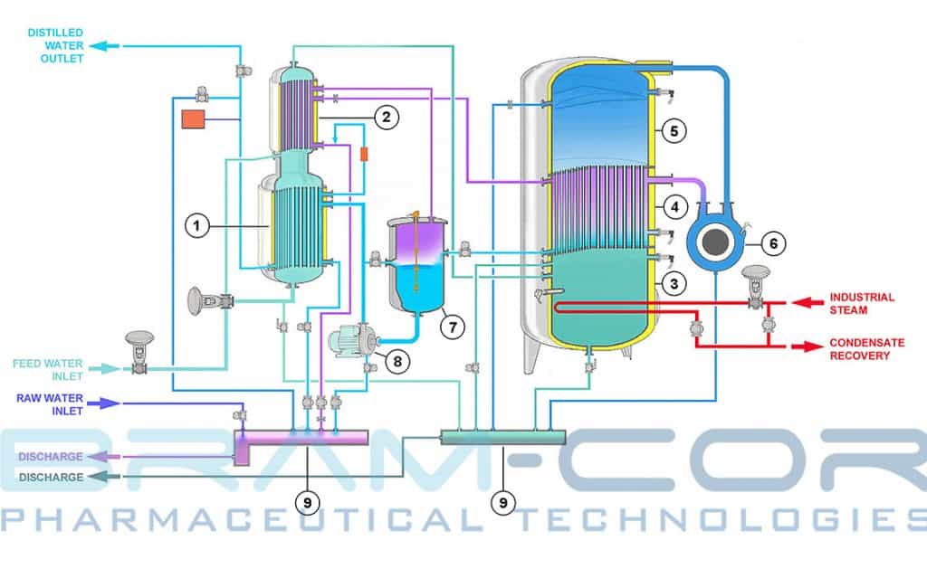

BRAM-COR STMC Vapor Compression Distillation process runs as follows:
STEP 1 Feed-water enters into the first (optional) heat exchanger (1) (tube side) and is pre-heated, cooling at the same time the WFI to the temperature set in the HMI.
STEP 2 An automatic system (optional) regulates feed-water flow passing through phase 1, thus regulating WFI temperature.
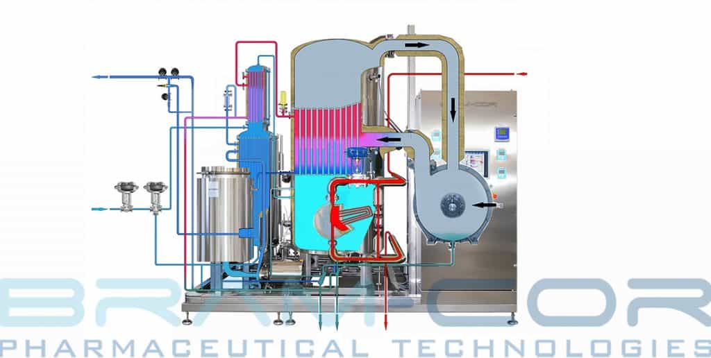
STEP 3 Feed water goes into in the second heat exchanger (2) (tube side), and is furthermore pre-heated, condensing the gas generated by WFI production process.
STEP 4 Heated water flows in tank (3). Water level is controlled by an automatic system. The pipes in condenser (4) are partially filled by feed-water.
STEP 5 The heater (either electric and/or steam-heated) increases feed-water temperature to evaporation temperature. The generated pure steam occupies the dome (5). An automatic system regulates the thermal intake of the heating system, in order to keep the pressure in the dome at the set value.
STEP 6 A blower (6) sucks in the pure steam present in the dome (5) compressing it into the shell side of the condenser.
STEP 7 Pure steam condenses in the shell side of the condenser (generating WFI) yielding energy to the feed-water contained in the condenser pipes, which now evaporates, generating other pure steam.
STEP 8 The produced WFI comes out of the condenser and flows into the recirculating tank (7). The gases released during WFI production process go into the shell side of the heat exchanger (2).
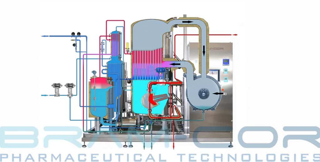
STEP 9 WFI is then collected in the recirculating tank (7) and pressurized by the pump (8), through the heat exchanger (1) (optional), where it reaches the temperature, setup in the HMI.
STEP 10 A measuring system continuously monitors WFI quality (conductivity and temperature), and diverts WFI to the storage tank (conform WFI) or to the distiller drain manifolds (9) (substandard WFI).